Airspace around the
Isle of Man
The Airways and Advisory
routes around the Isle of Man remained much as in the late 1970s, under
the control of Manchester Centre, although Delta White 11 had now been
re-aligned via the 'IOM' VOR. The old airway 75 KHz Marker Beacons originally
associated with the Radio Ranges had gone and the NDBs backing up the VOR/DMEs
started to disappear, although on the 1982 Airways Chart there is still
an NDB at Cregneash coding 'IOM' on 391 KHz. Of interest on the topographical
chart is the the Jurby bombing range D404 has expanded and is shown active
up to 11,000 ft, occasionally 20,000ft. The Eskmeals gunnery range D406
has 'grown' its first westerly extension towards the Isle of Man, D406B.
Ronaldsway's Control Zone has been reduced to the southwest but gained
three small Control Areas to the southeast by airway Red Three, probably
as a consequence of the base level of the airway being raised to Flight
Level 50. This would allow non pressurized aircraft to use a lower descent
rate for the comfort of passengers.
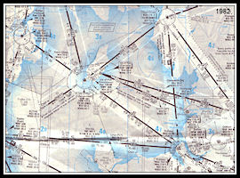 Airways Chart from
1982
Airways Chart from
1982
|
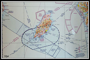 Topographical Chart
from 1984
Topographical Chart
from 1984
|
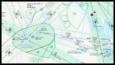 RAF Airways chart
from 1985
RAF Airways chart
from 1985
|
|
|
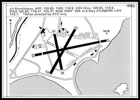
1982 Airfield Diagram
Operating with three
runways giving six landing directions, 27/09, 22/04 and 18/36. The former
runway 31/13 formed the Central Taxiway.
|
Ronaldsway Radar
Upgraded
In the early 1980s the
AR-1 radar installed in 1966 was given a major upgrade, essentially making
it into an AR-15. A new metal radar desk was built to accommodate larger
displays, the wooden 'Approach' section of the old Approach/Radar desk
being incorporated.
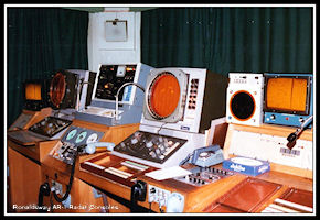 Ronaldsway AR-1 console
pre-upgrade
Ronaldsway AR-1 console
pre-upgrade
|
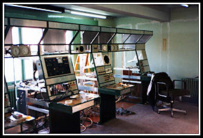 The new radar desk
under construction
The new radar desk
under construction
|
(Above pictures courtesy
N. Wilshaw)
Around this time another
radio frequency was allocated to Ronaldsway, 125.3 MHz. This enabled a
total of four operational positions to be active at the same time on busy
TT Race days. For the morning inbound rush, Approach on 120.85, Radar 1
on 118.2 and Radar 2 on 125.3 operational in the radar room with Tower
on 118.9. For the evening departure rush, Ground Movement Control on 118.9
and Air Control on 125.3 in the Tower and Approach on 120.85 with Radar
1 on 118.2 'downstairs'.
|
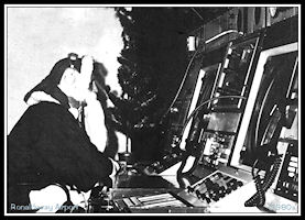
Ronaldsway New Radar
Desk
The new metal desk with
larger radar displays
'Santa Claus' seems
to be controlling at Rad 2
(From an ATC Christmas
card!)
|
|
There were four operational
positions provided on the new Approach/Radar desk; on the right of the
desk was the Approach Assistant, with the Procedural Approach controller
to his left. Next to him was the Radar One position with Radar Two on the
far left of the desk. Apart from the larger displays, the major improvement
from the radar controllers perspective was that the displays now had 'Video
Mapping'. This produced a map of the airways and reporting points on the
radar display, together with final approach tracks marked with distances
from touchdown for runways 27/09, 04 and 36. The final approach
track was not provided for runways 18 or 21 as there were no instrument
approaches to these runways. A coastline map was also provided for England,
Wales, Scotland and Ireland, but not for the Isle of Man - apparently it
was considered that it would clutter the display.
|
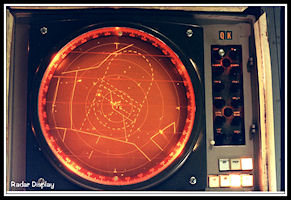
Phosphor Radar Display
Similar to the displays
used at Ronaldsway
with the upgraded AR-1
radar. Video mapping
to show controlled airspace
boundaries.
This actual display
was installed at Prestwick Airport, Scotland
|
When an inbound flight
was within about 50 miles from Ronaldsway the Manchester Centre controller
would call approach by phone and request an inbound level and clearance
limit. If there was no conflicting traffic Approach might clear the aircraft
to a relevant holding facility, e.g. CAR or IOM at 3000 ft altitude and
pass the Ronaldsway QNH (pressure setting to indicate height above sea
level). The Manchester controller would read the clearance back and add
the release point, e.g. 'Released passing Flight Level Niner Zero'
When the aircraft was transferred by Manchester and checked in with Ronaldsway
on 120.85, the Approach controller would confirm the procedural clearance
and pass the latest weather report and runway in use. If the flight was
to be radar vectored he would usually then hand the Flight Progress Strip
to the radar controller, effectively transferring control. Under normal
circumstances both Approach and Radar 1 controllers would use frequency
120.85, Radar 2 being opened on 118.2 only in busy traffic situations.
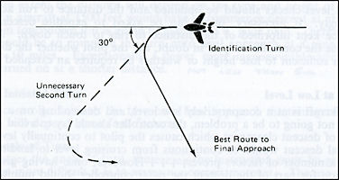
Radar Identifying
and Vectoring the Aircraft
The radar controller
would have used the VHF Radio Direction Finder (D/F) to select one of the
various 'blips' on his radar display as the most likely candidate for the
aircraft whilst it was talking to Approach but then had to formally identify
the aircraft using one of several methods. Probably the easiest was to
ask for a 'Radial and DME from the IOM'. The pilot would respond with,
for instance, 'IOM 130 radial at 33 miles' and the controller would check
that this corresponded with a blip on the radar display, making sure that
there were no others it could be confused with. The other common method
used was to identify by turning the aircraft. Having observed the likely
blip for a period of time and confirmed the aircraft heading with the pilot,
the controller would instruct a turn to the left or right of at least 30
degrees and then check that the selected blip had indeed turned after the
pilot confirmed steady on the new heading. After identification by this
method, the pilot had to be informed of his position as observed on radar,
this was a 'cross check' that the correct blip had been identified.
|
The Identificaction
Turn - if possible towards final approach
|
|
If for any reason the
blip was not identified, the pilot would be informed and instructed to
resume his own navigation. Other methods that could be used were a position
report over a published Reporting Point or a 'Radar Handover' where another
unit would confirm the identity of the aircraft using a common reference
point marked on both radar displays. Following identification the controller
could vector the aircraft, usually to the Instrument Landing System (ILS)
on runway 27 or for a Surveillance Radar Approach (SRA) to runway 09 or
04.
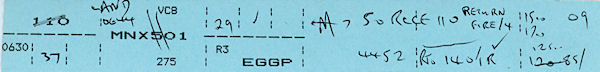
Flight Progress Strips
All flights had a Flight
Progress strip prepared, which were colour coded, Blue for departures,
Buff for arrivals, Green for local flights and Pink for overflights. Originally
the strips were all hand-written but Senior Air Traffic Control Officer
Dave Jeffers devised a system for printing the Flight Progress Strips onto
coloured card using a 'BBC' home computer. This was not a 'live' system
as strips were only printed in advance for the known scheduled flights
of the day, any other flights still had hand written strips. Some example
strips are below, preserved as they had been attached to 'Occurrence Reports'
for various incidents and retained on file. Normally the strips were only
saved for one month.
|
Outbound Flight Progress
Strip for Manx 501, a Viscount to Liverpool (returned with engine fire)
|
|
|
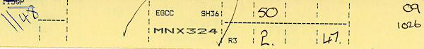
Inbound flight Progress
Strip - Manx 324, a Short 360 from Manchester
|
|
|
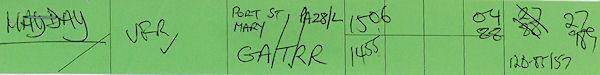
Local Flight Progress
Strip - G-ATRR a Piper Cherokee (Returned with an emergency)
|
|
|
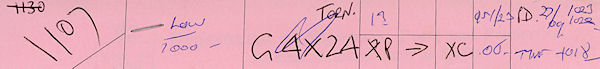
Overflight Flight
Progress Strip - RAF Tornado 'G4X24' from Scampton to Coningsby
|
|
The Control Tower
Accommodation Expanded
About 1983 a further
annexe was added to the tower, this time to the eastern end of the radar
room.
A proper fire escape
was also added to the building, replacing the former vertical ladders.
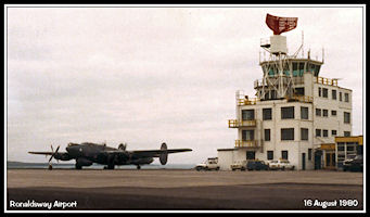 Control Tower in
1980
RAF AEW Avro Shackleton
Control Tower in
1980
RAF AEW Avro Shackleton
|
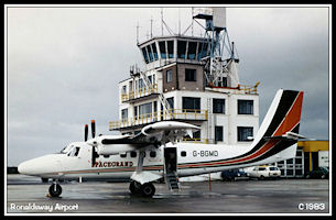 Control Tower in
1983
Spacegrand Twin Otter
G-BGMD
Control Tower in
1983
Spacegrand Twin Otter
G-BGMD
|
Radar Turning Gear
Replaced
Right at the end of
the decade in 1989, the radar turning gear needed replaced, necessitating
the removal of the radar scanner and
reversion to Procedural
Approach service whilst the work was taking place.
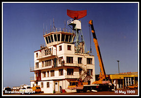 Crane for removing
the Radar Scanner
Crane for removing
the Radar Scanner
|
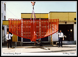 AR-1 Radar Aerial
at ground level
AR-1 Radar Aerial
at ground level
|
ATC
in the 1990s
|